

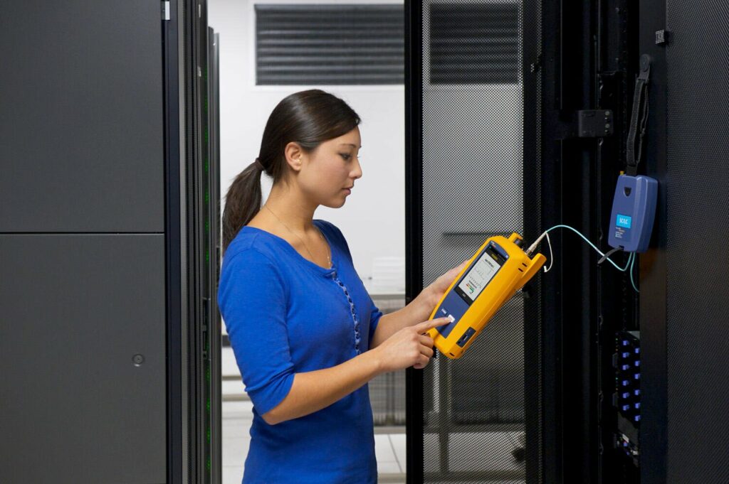
OTDR and Fiber Certification
This page is only about proving a fiber link and documenting the proof. Nothing here designs a route or installs a cable — that is fiber optic installation and, outdoors, campus and outside-plant fiber. Nothing here makes a joint either; splice technique and end-face preparation are on fusion splicing and fiber termination. What follows is the test regime: which instrument answers which question, what limit the results are judged against, and what the closeout package has to contain to be worth keeping.
Two tiers, two different questions
Tier 1 certification is an optical loss test set measurement: insertion loss on the link, plus length and polarity. That number is the pass or fail against the loss budget, and when a specification says a link is certified, this is usually the evidence it means. Tier 2 adds an OTDR trace, which reports where along the fiber the loss sits and what caused it.
The two are not interchangeable. An OTDR characterizes distance and events by reading backscatter from a single end; it estimates. A loss test set puts known light in one end and measures what arrives at the other. When the specification calls for insertion-loss certification, the trace supports the result but does not replace it.
The reference method changes the number
How the test cords are referenced decides which connectors are inside the measurement. A one-jumper reference includes the connector at each end of the link, which is what an owner normally wants to know. A three-jumper reference excludes them and reports a lower loss for the identical link. Agree on the method before the first result is saved, or the results from two crews on the same job will not compare. Multimode testing under TIA-526-14 also depends on a compliant launch condition, and single-mode testing follows TIA-526-7. Test at both wavelengths for the fiber type — 850 and 1300 nm on multimode, 1310 and 1550 nm on single-mode — because bend-related loss shows up at the longer wavelength first.
The loss budget is the acceptance criterion
A budget is built from the fiber’s attenuation over the measured length, plus an allowance for each mated connector pair, plus an allowance for each splice. Two things have to be settled before testing starts: which limit applies, and how the connections are counted. A standards-based component limit and an application budget for the specific transceiver are different numbers, and a link can pass one while failing the other. Deciding that at closeout, with crews demobilized, is the expensive way to find out.
What the OTDR setup decides for you
Trace quality is set before the first shot. Pulse width trades resolution against reach: a short pulse gives tight dead zones and separates close events, a long pulse reaches farther but merges events into one. Range, averaging time, and the refractive index entered for the fiber all affect the result, and a wrong index puts every event at a wrong distance. A launch cord is what makes the first connector visible and measurable; a receive or tail cord does the same for the last one. Without both, the two connectors most likely to be the problem are the two the trace cannot report.
Why bidirectional testing exists
Backscatter differs slightly on either side of a joint between fibers that are not identical, so the same splice can read low from one end and high from the other, sometimes as apparent gain. Averaging the two directions gives the real value. Any job where individual splice loss is a contract number, and most outside-plant work, should be tested both ways.
What the documentation has to show
- Native trace files and the loss test set results, not only a summary print
- The setup behind them: wavelengths, pulse width, range, averaging, refractive index, and launch and receive cord lengths
- The limit selected and the reference method used, stated once and applied to every strand
- Strand identifiers that match the labels physically on the panels and closures
- An exception log: what failed, what was done about it, and the retest result
- Date, instrument, and calibration status for each set of results
On multi-state rollouts this consistency does the real work. When crews in Charlotte, Atlanta, and New York save results under the same limit, the same reference method, and the same naming, the package reads as one system instead of three. Call (888) 360-0035 to set a test plan before field work starts.